Two-Sided Machining
Cut2D Desktop has the ability to create a project where your design requires you to cut both sides of your material. Typically you will cut the top surface of your material, then manually turn the material block over on your machine, whilst maintaining a common registration position, and cut the bottom surface using a second set of toolpaths. By specifying a two-sided project using the Job Setup form and indicating how you intend to flip the material over on your machine, you can allow the registration and organisation of the geometry, toolpaths and previews relating to each side of the design to be managed by the software. During the design process you can then switch between the top and bottom surface of your design, create toolpaths for each side and view a preview of the material - including after it has been cut from both directions. Once you are happy with the result you can then save the toolpaths relating to each side independently.
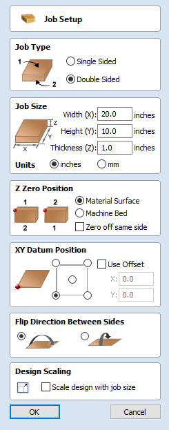
Two-Sided Job Setup
In the Job Setup dialog, you can pick whether you want to create a single-sided or a double-sided job. You can change this setting later if you wish.
The initial Z-Zero Position you will be using for the toolpaths relating to each side is set from the Job Setup dialog. You can choose to Z-Zero from the same material surface for both sides, the machine bed for both sides or you can opt to Z-Zero from each side indepenendently. Your choice depends on the nature of your design. Typically, if you are only intending to carve into the surface on each side then you will Z-Zero each independently after you have physically positioned the material on your machine. If your design involves cutting through the material and the Z depths for each side must coincide precisely, however, then you will usually wish to use a common Z position for both sides. You can change the Z-Zero settings for each side subsequently using the Material Setup form.
The X Y Datum Position applies to both sides of the material.
In order to correctly manage the alignment of the geometry relating to each side, it is important that the software knows whether material will be flipped vertically or horizontally during the physical machining process. Flip Direction Between Sides determines the automatic transformation of the drawings, models or toolpaths associated with each side. If the material block will be flipped horizontally then the software will automatically mirror your data to mimick the relative positions each side.
When you create or open a two-sided project, Cut2D Desktop will display two new icons in the 2D View Toolbar. The first icon indicates which flip direction option has been specified for this project. It will ininitially be set to display the Top Side of your design. Any drawing or toolpath creation will be associated with the Top Side and this is known as the active side. To work on the other side of your design you will first need to make the Bottom Side active. Click on the Toggle Side button in the View Toolbar to switch the active side between top and bottom. Alternatively, you can use the number key shortcuts: 1 will make Top Side active and pressing 2 will make the Bottom Side active.
Two-Sided Toolpath Management
When toolpaths are created in a two-sided job they are automatically associated with the active side from which they were created. This helps you to keep track of which side of your job each toolpath is for. The toolpath list will only display the toolpaths for the current active side and this is indicated in the heading, which will read Toolpaths (Top) or Toolpaths (Bottom) accordingly. Changing the active side (using 1 or 2, for example) will cause the toolpaths list to also swap the displayed set of toolpaths.
Two-Sided Toolpath Previewing
The Preview Toolpaths form now includes a button. This will simulate toolpaths cutting both sides of your job (regardless of the currently active side) so that you can see the combined result of your toolpaths in a single, solid, 3D representation of the final job.
Two-Sided Toolpath Saving
Saving your toolpaths from a two-sided job is done independently for each side. Save the toolpaths for the currently active side, then make the other side active (using 1 or 2) and save out the toolpaths for the other side.